Octopus Badges
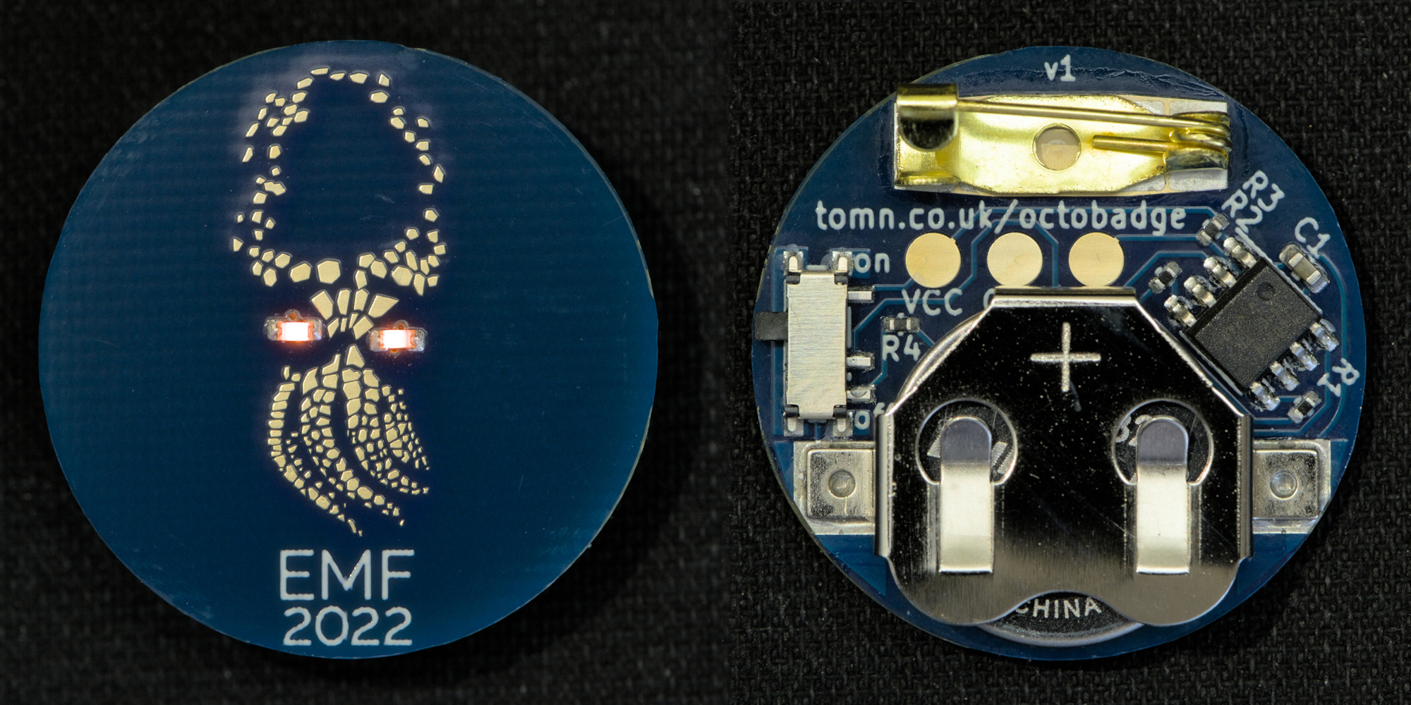
100 tiny octopus badges with glowing LED eyes were made for an egg hunt at EMF. This page contains some basic information for badge owners and assembly instructions for the badge kit.
If you would like one and are at EMF, follow @neptunesgachapon on twitter (or nitter). or instagram (or bibliogram) for clues.
Information
The badges use CR1632 coin cells, and should run for about 8 days continuously (designed for at least 4).
There is no reverse polarity protection (for good reasons); the coin cell must be inserted the correct way up (+ facing out), though empirical evidence suggests that they will survive if it’s reversed.
Badges are not waterproof, and should not be stored with anything electrically conductive.
The firmware was written in a rush so is not very good. To reset a badge if it stops working because the firmware has crashed, remove and replace the battery.
Assembly Instructions
If you’re reading this you might have found the badge kit.
This was more of a joke than a serious attempt to make a nice kit. It should be possible to assemble by hand, but it uses 0402-size passives, so it probably isn’t the best way to get started with SMD soldering.
For placement and values of components, see this page (generated with InteractiveHtmlBom, requires javascript).
Kit contents:
- 1x badge PCB
- 4x 1k5 0402 resistors (labeled white tape)
- 4x 4k7 0402 resistors (labeled white tape)
- 2x 2u2 0603 chip capacitor (unlabeled white tape)
- 4x ROHM SML-D12D1WT86 LEDs (unlabeled black tape)
- 1x pre-programmed ATtiny402 MCU
- 1x SPDT switch (PCM12 imitation with the locating pins removed)
- 1x brooch pin
- 1x battery clip
- 1x CR1632 coin cell
Some tips:
- Turn on Highlight first pin in the settings to see the orientation of U1.
- The order of components should be approximately right, though you might find it easier to place U1 before the passives.
- The kit contains twice as many of the small components as required, so that it can still be assembled if you lose some. Keep half in the tape in case this happens!
- The LEDs should be placed with the small green triangle on the bottom pointing towards the centre (pin 1). These can alternatively be identified from the top as the pads are shaped slightly differently (see the image on the first page of the datasheet), or with a multimeter (pin 1 is negative).
- The battery clip should be placed with the opening facing downwards.
- The pin should be placed with the hook pointing downwards.
Good luck!
Attribution and Disclaimer
This project is not associated with EMF; we did it because we thought it would be fun, were not funded by EMF, and gave the badges away for free.
The design is based on this image (alternative and archive). If you took this get in touch and I can maybe send you a badge?
The badge was designed using kicad and inkscape, and panellised using kikit.