Making Bike Lights Work Better with NiMH Cells
This page describes a simple mod to make a bike light work better with rechargeable NiMH cells.
The Problem
I use a brompton rear light which works nicely when powered by 2 alkaline AAA cells. Unfortunately it’s quite a lot dimmer with NiMH cells because of the lower voltage.
The circuit for the LED driver looks something like this:
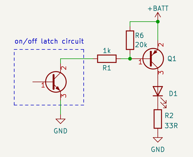
The LED is switched by a high-side PNP transistor, which is controlled by the latch IC. Why it’s done this way is not exactly clear; perhaps the transistor in the IC is not very strong, though the LED is only driven with about 30mA.
The issue is that the LED has a forward voltage of about 2V at 30mA, so the current (and therefore the brightness) will vary linearly with the voltage, starting with 0mA at about 2V.
The voltage of alkaline and NiMH cells drop as they are discharged, and this means that the brightness will drop too. The voltage vs. time for both kinds with a constant current discharge looks something like this:
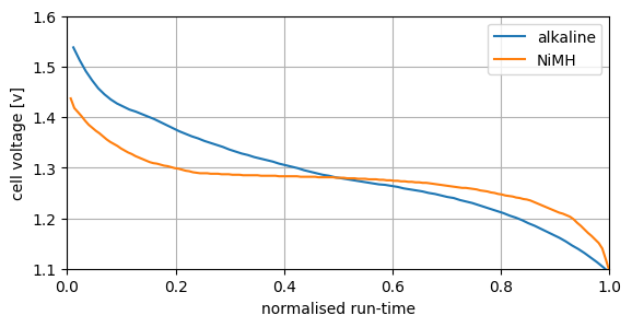
To use most of the energy from these cells the voltages need to be taken down to around 1.1V, and so the light will be bright with fresh cells, then spend lots of time at a lower brightness (as less current is used, stretching the curves to the right).
The shape of this was unexpected to me — I thought that NiMH cells would have a lower average voltage across their full discharge curve than alkaline cells, since that’s normally the reason given why things don’t work as well with NiMH cells, but actually any device designed to use all energy from an alkaline cell should work just as well with NiMH.
Anyway, a more constant LED current would obviously be better (since we’d get more time at a reasonable brightness), so let’s try to achieve that.
The Solution
Thanks to the slightly odd circuitry, it’s easy to improve by using Q1 in its active region rather than in saturation:
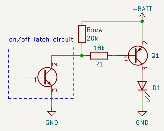
- R1 is replaced by a much higher value, calculated from the approximate gain of the transistor and the desired LED current (taking into account the 0.6v drop across Q1), then adjusted to match the gain of the specific transistor.
- R6 is removed and replaced with Rnew; it’s still important to make sure the transistor stays off when it should, but this way it doesn’t interfere with the regulation.
- R2 is removed (or bridged), as it now serves no purpose except to make the low-voltage cut-off worse.
Of course the base current (and therefore the LED current and brightness) will still vary with voltage, but it will vary a lot less in the range we’re interested in (zero around 0.6V rather than 2V as before). This seems to work quite well — the current only varies by a few mA between 2.2V and 3V.
The Implementation
Before:
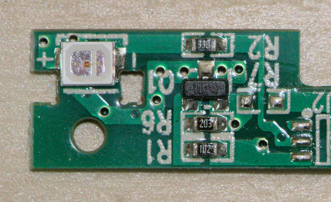
(taken before I decided to write this — gross!)
After:
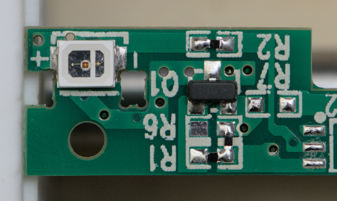
It was slightly easier to replace R2 with a zero-ohm link. 0805 resistors would probably have been better than 0402, but they looked a bit big at the time.