Building a Tiny CNC Router for Making Circuit Boards
I built a tiny CNC router for making circuit boards, and more. It has a working volume of 106 x 104 x 20 mm [0] and occupies a space of about 300 x 250 x 200 mm.
It can be used to make FR4 circuit boards with 0.5 mm pitch components, and can cut aluminium.

Here are two example circuit boards, and experiments in acrylic and aluminium:

Motivation
I saw Scanlime using a Bantam Tools desktop milling machine to make a circuit board on a live stream. It looked so convenient, and I couldn’t get the idea of having something like that out of my head.
Of course, CNC milling is objectively the worst way to obtain circuit boards by most metrics.
PCB prototyping services are cheaper, have better capabilities, and are more convenient. On the other hand, I find that being slow (say, a week vs. an hour), paying every time, and paying for board area tends to make me procrastinate and spend lots of time perfecting and checking designs.
Etching is definitely cheaper and can achieve higher quality, but requires dealing with dangerous chemicals (not ideal in a carpeted rented flat…), is a single-purpose process, and also requires a fair amount of stuff. In some ways, the capabilities are worse, as a router can naturally make nice board outlines, mounting holes, and slots. In some ways, making double-sided boards is also easier than using etching.
The router mainly competes against hand-wiring prototypes/one-off projects on perfboard, which I find to be tedious. It always takes longer than I expect, and the result is often unsatisfying as it’s very easy to make mistakes, which are messy to fix. Perfboard prototypes are also just not very good in today’s world where all components are surface-mount and all signals are high frequency.
I’ve also been lurking in the hobby CNC community for a while, and wanted a piece of the action. I don’t have the space for big second hand junk, so tiny first-hand junk will have to do.
Criteria
My approximate design goals were:
Working area: at least 100 x 100 mm.
Working height: enough for a circuit board, work-holding and a spoil-board, ~15 mm.
Tools: able to use standard 38.1 x 3.175 mm tooling, with enough travel to change tools over the workpiece.
All performance aspects (motion system stiffness, maximum force, backlash, and resolution; spindle speed, power and run-out etc) enough for:
- FR4 isolation routing (high RPM, 0.1 mm resolution on X and Y, 0.01 mm resolution on Z)
- FR4 cut-out in a reasonable time
- cutting aluminium would be nice
Small and light enough to be easily moved around and stored when not in use.
I had a look around for off-the-shelf machines; everything I found was too big and too expensive for the capabilities I wanted. The old Bantam Tools milling machines looked appropriate, but they don’t make them any more, and they were expensive for what they are.
I also spent a while looking at existing designs. Most generic machines are too big. “The Ant” looks quite close. The resulting circuit boards look nice, but there are some aspects which seem less sturdy than I’d like. I’m also not keen on building on top of a proprietary design: the design sources are not available, only the outputs.
Motion System Design
Here’s the machine labelled with terminology and axis names:

It’s a gantry-style machine built from 2020 aluminium extrusion. The X and Z axes use a single MGN12H (clone) linear rail and carriage, while the Y axis uses two. The X and Y axes are driven by belts, which are directly driven by NEMA17 0.9 degree stepper motors. The Z axis uses a lead-screw and anti-backlash nut driven by a small NEMA14 stepper motor.
This sounds quite flimsy by conventional standards, barely different from a 3D printer, but in reality it’s stiff enough to meet the above criteria.
The rationale for this is as follows:
The whole machine is tiny, for example the gantry is only 205 mm long between supports. Since the deflection of a beam in three point loading is proportional to its length cubed, this makes a big difference — making the X axis 50 mm longer would approximately halve the stiffness of the frame. This also makes the belts short, which helps.
The motion system was designed so that the cutting forces are generated as close to the rails as possible, to minimise torque. The X axis rail sees the most torque, but is still only 50 mm away from the typical cutter position.
Without measuring, the X axis rail is a good candidate for an upgrade — the simplest option would be to replace the gantry with a 20 x 40 mm extrusion, and use two MGN9 rails with two blocks each, which are smaller but can sit side-by-side.
Belt drives were chosen for X and Y because they are cheap, compact, simple and inherently zero-backlash. To make it stiff, I used large stepper motors, a 10 mm GT2 belt, small 16 tooth pulleys, and high belt tension.
The steppers have a holding torque of 46 N.cm, or 90 N with a 16 tooth pulley.
0.9 degree steppers are chosen (as opposed to the normal 1.8 degree) because for the same holding torque a stepper with twice the steps is twice as stiff. This is because the torque of a stepper is sinusoidal with resect to the shaft angle, with the period defined by the step size. Increased resolution is nice too (0.08 mm, or 0.005 mm with 16x microstepping).
Using stepper motors with integrated lead screws might have been similarly complex, but are expensive and often have unclear specifications.
Using a lead screw for the Z axis gives more resolution where it’s useful, reduces the weight of the carriage, and keeps the Z position when the motors are powered down. The force on Z is mostly in one direction (up) in the cases I care about, so the anti-backlash provision can be weak.
There are a few 3D printed parts in the motion system.
The belt clamps are printed, and are long enough that stiffness is not a concern (though the toothed part should be replaced with aluminium):
The idler/tensioner is also printed:
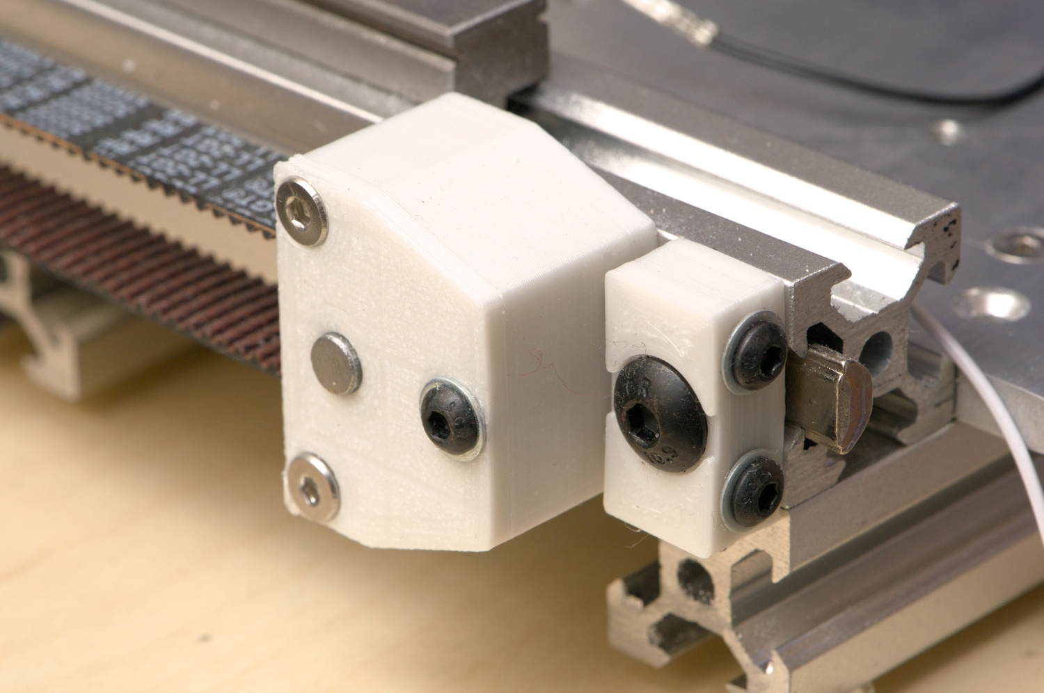
The odd design is to deal with high tension in a small space. The left and right part are both mounted to the frame with one screw, and there are two screws connecting them. The screws in the right block are used to tension the belt, while the screw in the left block is used to keep it parallel with the frame (and is loosened when tensioning the belt). Despite the high tension, creepage has not been an issue.
Z Axis
The anti-backlash nut on the Z axis is also printed:
I intended to use an off-the-shelf nut, but struggled to find one that would fit in the space. In the end it was easier to just buy a tap and make one. It works well enough, but definitely needs a re-think: the flexure design is kind of neat but completely unnecessary in practice, the spring is only provided by the flex in the plastic, and the bottom mounting screw is completely blocked and requires disassembly to access.
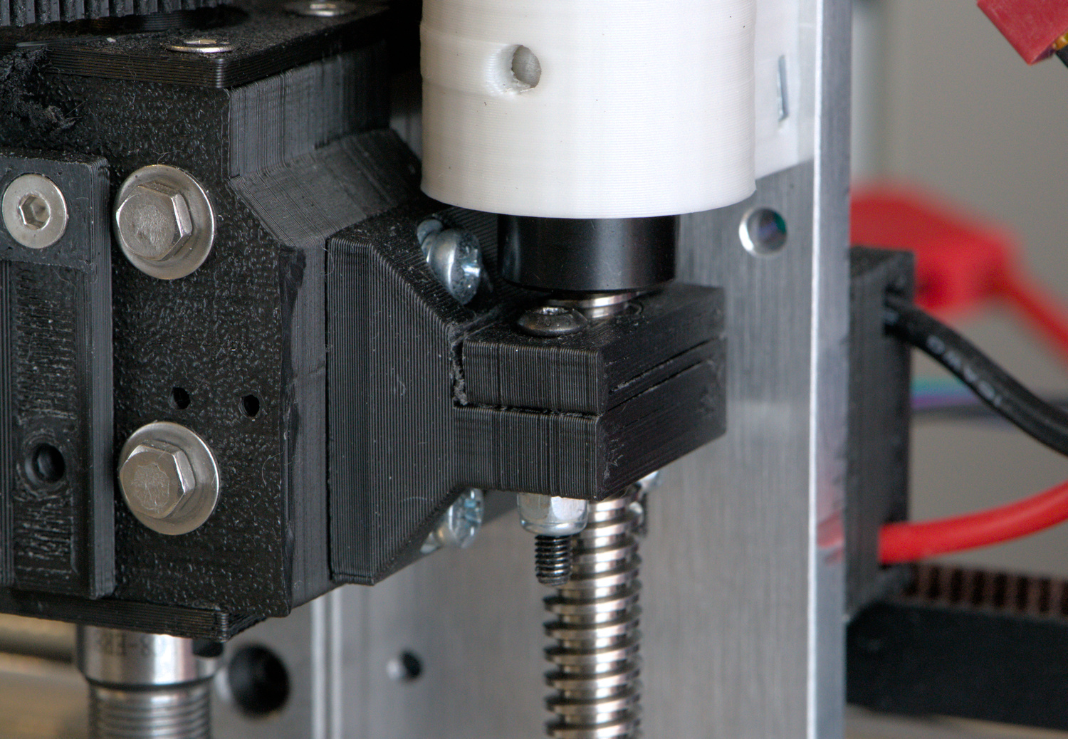
The Z axis motor mount/thrust bearing is also “interesting”. Inside it looks like this:

The shaft coupler joins the motor shaft to the lead screw. It is a flexible “beam” type, and is stretched when installed to tension the whole arrangement and eliminate backlash (the shaft collar on the lead screw pushes the bearing into the bottom of the mount).
This is odd, but more compact than any conventional lead-screw bearing arrangement I could find, and was built from parts I already had. The main issue is the inappropriate use of a ball bearing; that will be replaced by an angular contact bearing soon.
Spindle
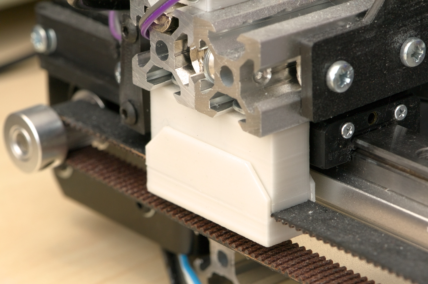
The current spindle iteration is built around an ER8 collet “extension rod”, which is just a collet chuck on the end of an 8 mm shaft, typically sold for use in real milling machines, to use small cutters in inaccessible places. The spindle is driven by a brushless outrunner motor, via a flat belt running on a crowned pulley:
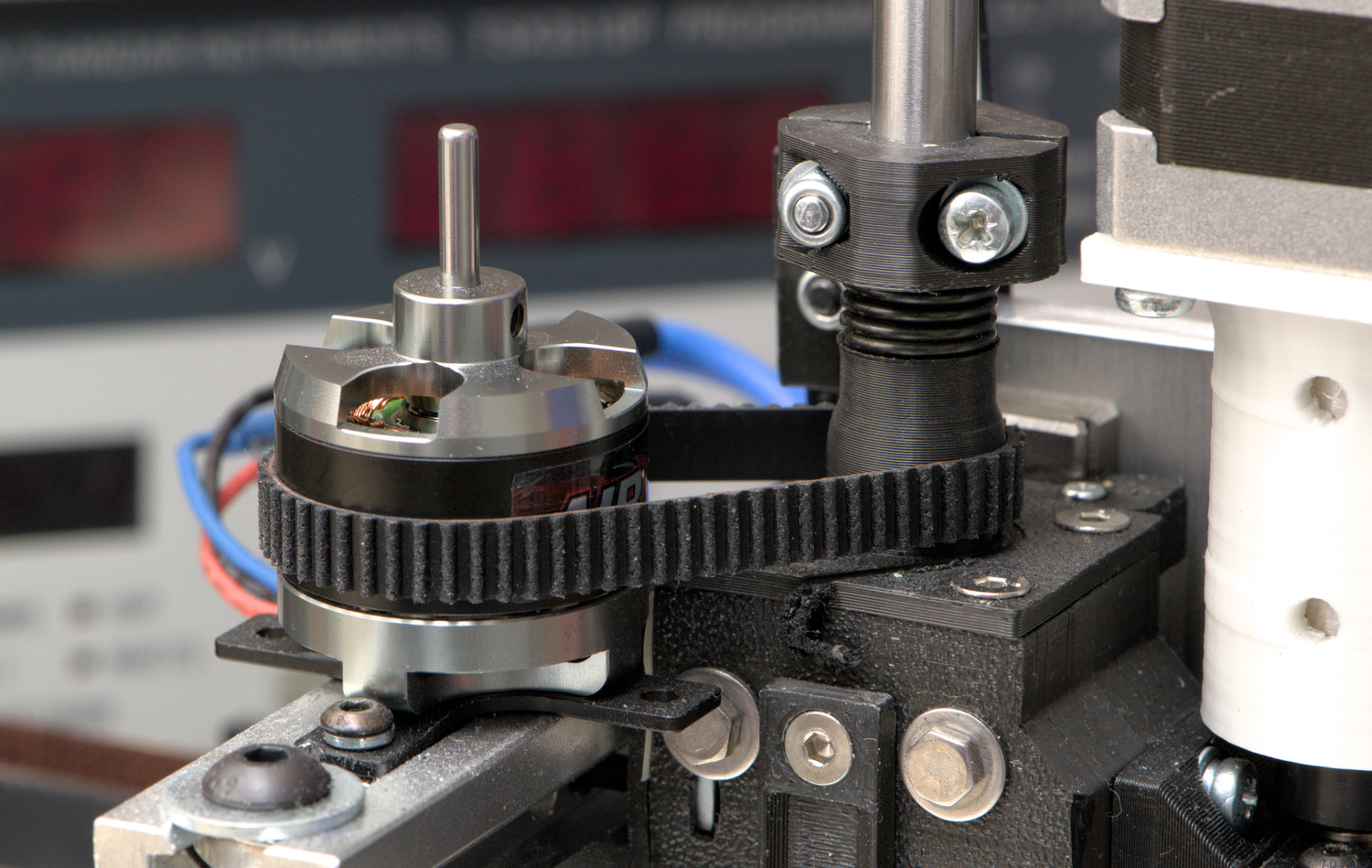
The spindle runs on two angular contact bearings, which are mounted in a 3D printed block. The block is screwed directly to the carriage of the Z linear rail. It’s split in two, so that the bearings are essentially clamped to the carriage by the mounting bolts, making it reasonably stiff.
The bearings are preloaded by a spring and a 3D printed shaft collar. A relatively low-rate spring is used because PLA has a high coefficient of thermal expansion, which causes problems if the spring rate is too high. The 3D printed collar is not a good idea, and will be replaced soon.
The drive belt is just a reversed 6 mm GT2 belt, which works, but I’d like to find a better solution. The main issue is that the belt is too wide for the crown, so the tracking adjustment is tricky.
The motor mount is also due for a redesign. The next version will have the motor mount and lead screw nut integrated into the spindle block.
Electronics
The whole thing is controlled by the board from an Ender 3 3D printer, which I already had. It’s adequate, except that the slow microcontroller restricts the choice of control software.
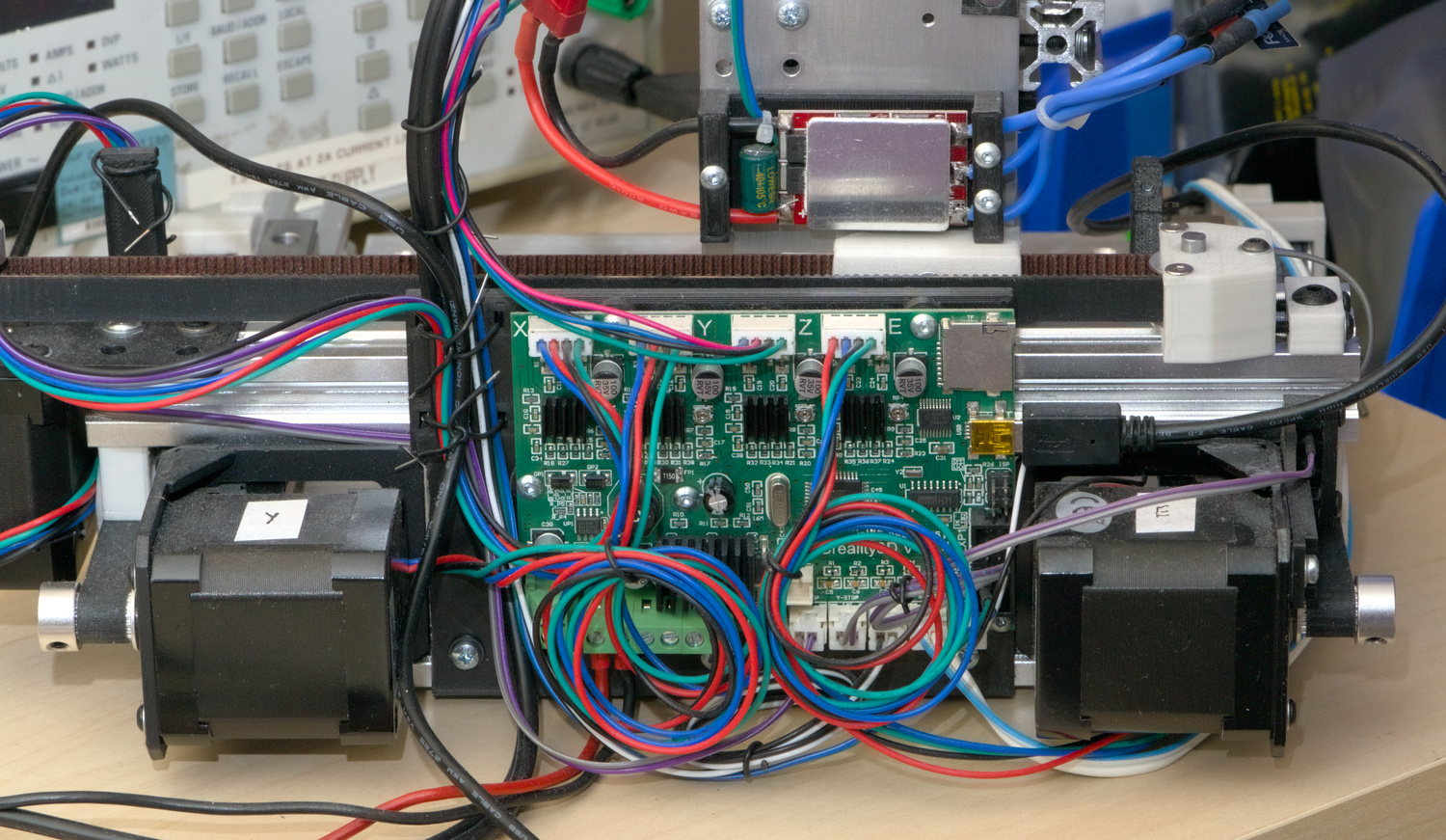
I made a few modifications to make this work better in this application.
The filters on the end-stop inputs were replaced — originally they had a 10k resistor to VCC and a 9.2uF capacitor to ground. With end-stop switches which short to ground, this is essentially a tiny spot-welder. It’s no wonder they eat end-stops.
I also shorted out the ROSC resistor on the X and Y axes to turn off the automatic mode selection on the A4988 stepper drivers, which didn’t seem to work well with these stepper motors.
The spindle motor is driven by a random ebay brushless speed controller. The main issue with this is that the speed controller, despite its name, does not actually control the speed. The motor speed is not directly related to the pulse width from the control board, and there is no speed feedback, so at the moment I’m limited to setting the speed in G-code in arbitrary PWM units and hoping for the best.
I’d like to include a spindle speed sensor in the next iteration, so that the controller can close the loop and detect stalls or belt issues.
Software
- The controller is running uCNC, which has lots of features and still runs on old microcontrollers. The only feature I really need over GRBL is the ability to have two motors on one axis (and even that could be fixed in hardware). I’ve experienced some bugs, but the developer is very active and they were fixed quickly.
I’m using bCNC to send G-code to the controller. It took a while to find this, it seems to be a hidden gem. I had a few small issues, but no show-stoppers (and some would probably not have been a problem if using GRBL). They are easy to resolve thanks to it being a straightforward python/tk project.
I’m using its height-mapping support, which I found to be more convenient than the one built in to uCNC, as it’s easy to set the area from loaded G-code, and has a nice visualisation of the results.
Its manual tool-change support is also good (if a little fiddly) — you can get it to pause the job, move to a specified tool change position, then probe to set the tool length offset or work coordinate system zero.
The support for using a camera on the spindle is fun, though also fiddly. Once calibrated, it can be used to find the position of features, in order to set a zero position, or even correct for rotation. In theory, this offers a nice workflow for making double-sided circuit boards, by isolation routing and drilling the first side, and using the drilled holes to align the second side.
In practice the alignment of the second side doesn’t need to be that accurate, so other methods are probably good enough and less faff. The one time I tried this I forgot to press the button which actually corrects the rotation, and it still worked well enough.
To turn the output of KiCad into G-code I’m using pcb2gcode. This is easy to use and works quite well, except for a bug in the current version which sometimes causes travel moves to cut traces — easy enough to work around, but annoying if you don’t spot it.
I’m not always happy with the tool-paths it generates, but it’s not really pcb2gcode that’s at fault. There is an inherent tension between reproducing the design as accurately as possible, and producing optimal tool-paths. For example, it will spend time squaring up the corners of thermal cut-outs, which is unnecessary, but that’s what it’s been told to do, and sometimes squaring up corners is necessary.
It’s not clear how it should work. I’d like to try making my own G-code generator, just to understand the problem better, but that’s obviously a massive time-sink.
A Better Controller?
While this all works, it could be better. The separation between controller and sender doesn’t make much sense to me. They are separate projects, written by different people, speaking a mix of unspecified protocols and a random subset of G-code, and it shows.
This arrangement is fine while the sender is sending a long uninterrupted stream of G-code (like in a 3D printer), but once you have operations where the user is in the loop (like a manual tool change) the two sides really need to understand each other properly. It mostly works, but feels janky, and is very bug-prone.
I think in contrast, there are some projects which get this right:
In Klipper, a server application interprets G-code to produce step/direction signals, which are compressed and sent over a serial port to a microcontroller, whose only job (or near enough) is to produce the step/direction signals and report its status. User interfaces talk to the server with a well-defined API.
This means there is only one G-code interpreter, it’s not running on a microcontroller (so doesn’t have to be optimised to work fast enough), and it doesn’t even have to run in real-time because the step/direction commands can be queued.
To implement probing, the server tells the microcontroller component to stop when a GPIO changes state.
Unfortunately it’s quite printer-specific and lacks a lot of features needed for CNC. The heavy step compression is also only needed to work with a slow microcontroller connected over a slow link, both of which are unnecessary limitations these days.
In LinuxCNC, a server produces a set of motor positions 1000 times a second. These are turned into step/direction signals either in software (for old-school parallel port operation), or by sending these positions to some hardware interface.
This is similar to Klipper, but the server runs in real-time — this is needed to implement operations like threading on a CNC lathe, but feels superfluous in this application. It’s not easy to just add a buffer, because probing is implemented in the server. This means that there’s two less than ideal options:
- Run the real-time server on my regular computer (which is also running KiCad/FreeCAD, a web browser, a million xterms etc. — not an ideal real-time environment), connected to some control board on the machine over ethernet or USB.
- Run the real-time server on an embedded computer attached to the machine, and run the GUI over X11-over-SSH, or using the LinuxCNC client/server mode. This is probably the sensible option, it just doesn’t sound like a fun time to me.
Tooling
For FR4, so far I’ve only been using ebay special engraving bits, milling cutters, and drills. Surprisingly all are actually tungsten carbide (based on density), but I’d only recommend the drills. The milling cutters arrived chipped and blunt, while the geometry of the engraving bits is essentially random — out of 10 only a few are usable.
This is a cheap way to see if it would work, but I ended up buying a range of bits from Fortex to try next time.
For aluminium and plastics I’ve been using single-flute end mills from the “DREANIQUE” store on aliexpress, which seem good.
For work-holding, I’m mostly using some 3D printed toe clamps which screw into M3 threaded holes in the base plate. This works well, except that when isolation routing a 10 x 10 cm circuit board the centre has enough flex that isolation routing needs to be deeper to work properly. One way around that would be to add some padding in the centre, and let the height mapping compensate.
Results
FR4 Circuit Boards
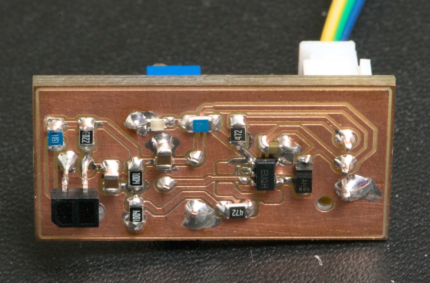
This was the first thing I made, just to test it out. It’s an amplifier for a reflective infrared sensor:
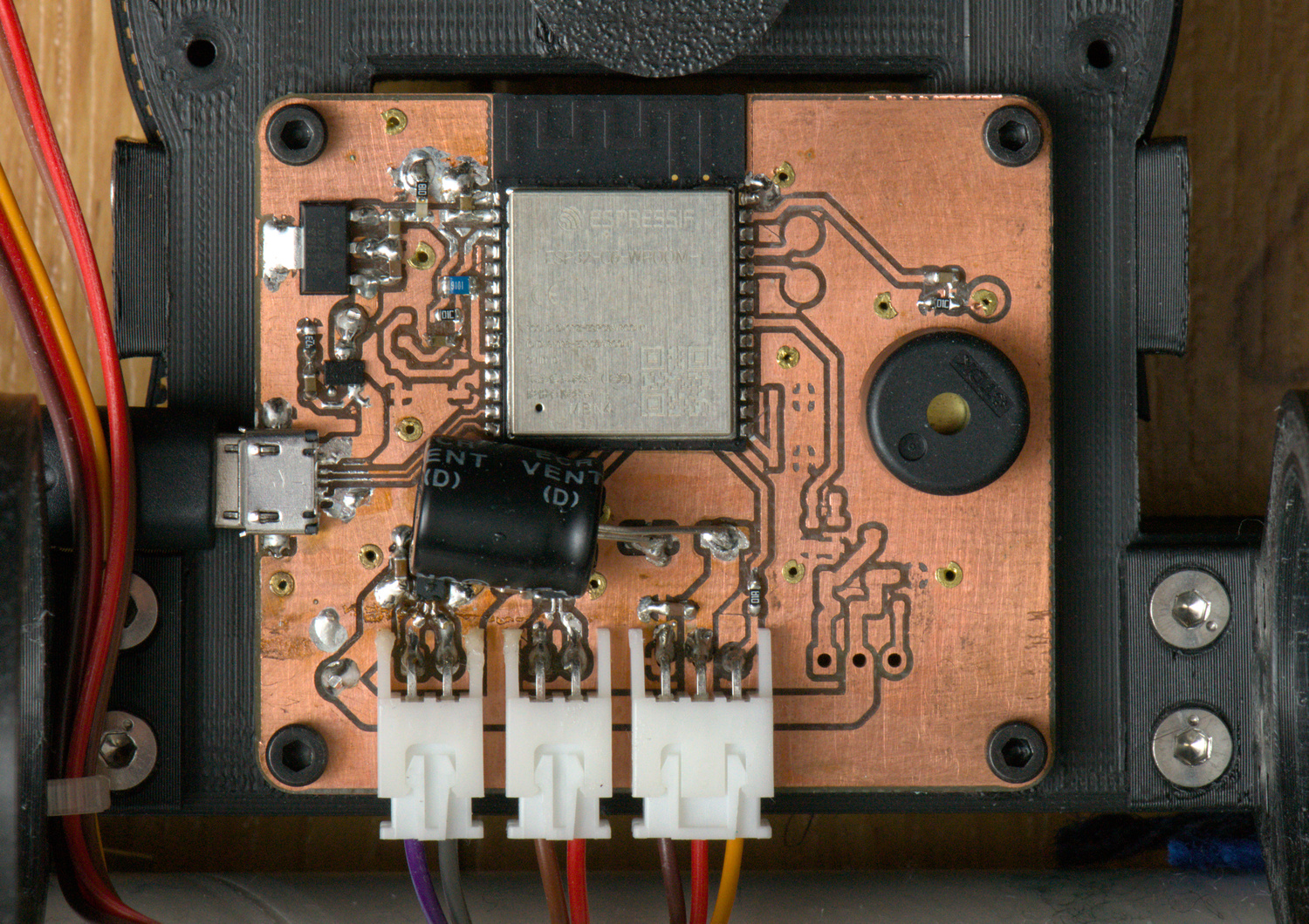
The most complicated thing I’ve made was this board for tidybot, with an ESP32-C6, a USB port for power/programming, an inrush current limiter circuit, two motor drivers, and some other bits and pieces.
This is double-sided, with vias provided by brass rivets. The back side is mostly ground plane.
The isolation routing and cut-out for this took about 10 minutes each. Babysitting the cut-out was quite unpleasant, as I’m currently manually adding soapy water to keep glass-fibre dust out of the air. With vacuum extraction and more speed (currently at only 100 mm/minute and 0.45 mm infeed) this could be viable.
I’m much more excited about this kind of thing though, a prototype DC-DC power supply built just to validate it for another project (complete with lots of wires, flux, oxidation and fluff):

The layout was thrown together without much care, ignoring any tricky to route traces and adding them with magnet wire after the fact. Isolation routing took 6 minutes, and with no cut-out or drilling steps the whole process was quick and easy.
The routing of the bits that matter (e.g. ground and power traces for these DC-DC converters) is much better than could be easily achieved with SMD adapters on a perfboard.
Acrylic
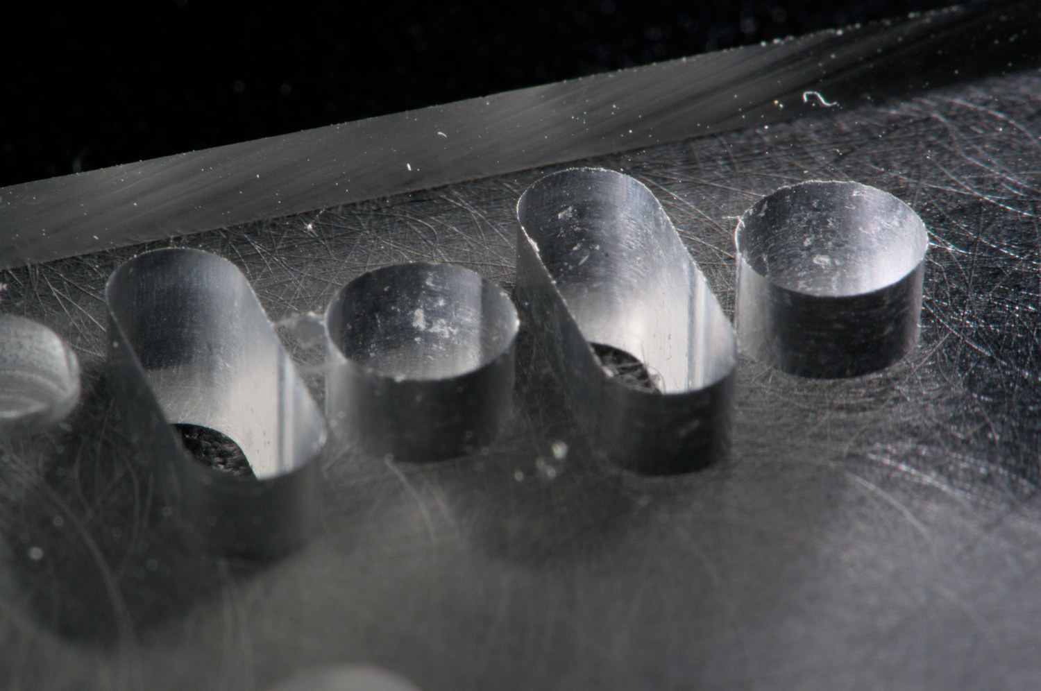
4 mm holes and 3 mm slots in acrylic, cut with a 2 mm single-flute end-mill.
These were cut at 1100 mm/minute and 20000 RPM for a chip load of about 0.05 mm. The left two are with a step-down of 0.75 mm, and the right 1 mm. Both seem happy, but chip evacuation is starting to be a problem, and some re-cutting is visible.
The hole used a single-pass helical path (100% width), while the slot used an offset path with a ramp entry dress-up, which makes it sound much happier.
Aluminium
A 5 mm wide 2 mm deep pocket and a 2 mm slot in mystery aluminium extrusion, cut with a 2 mm single-flute end-mill.
These were cut at 500 mm/minute and 20000 RPM for a chip load of about 0.025 mm, with a step-down of 0.2 mm.
The pocket used adaptive clearing and a 0.1 mm full-depth full-speed finishing pass, which was too much — some chatter is visible.
With some tweaking it could probably go a bit faster.
Cost
An approximate cost break-down, excluding the electronics might look something like this:
- 3x big stepper, small stepper, 2x right angle bracket, flat bracket, shaft coupler: £43 + £26 shipping = £70
- 3x 708C-P5 ACBB: £16
- 3x 150 mm MGN12H rail, 1x 100 mm MGN12H rail, 1x 2 mm lead T8 lead screw: £45
- 2m 10 mm GT2 belt, 3x 5 mm 20T 10 mm idlers, 3x 5 mm 16T 10 mm pulleys: £36
- C8-ER8A-100L chuck, ER8-3.175mm collet: £11
- 2m 2020 extrusion: £15+£9 shipping = £24
- L2210A-1650 motor, 20A ESC: ~£25
- 5 mm aluminium plate for bed, 6 mm for carriage: ~£20
- TR8x2 tap: £21
- misc hardware: £30
About £300 total. Where possible I used the Voron sourcing guide to find parts.
Conclusion
On one hand, the results of this project will never justify the cost, which is mostly the time I spent working on it.
On the other, I wanted to build a CNC machine, the outcome is pleasing and the process was fun. I took a risk on some unconventional design decisions, which seem to have paid off, as the machine meets or exceeds the expectations I had going into the project.
I’ve got some upgrades and projects with this machine planned; which I aim to post about here.
| [0] | 20 mm is the minimum space between the bed and the carriage, but the total z travel is 45 mm, and it’s possible to handle taller parts by removing the bed. |